Steam Tracing Specification
This article is sample engineering steam tracing specification that is used in construction project for industrial plant. It is indirectly is useful for site inspectors.
1. GENERAL
1.1. SCOPE
This Engineering Specification covers the minimum design and material requirements for steam tracing of process and utilities piping systems and equipment as shown on the P&IDs, UDDs and Interconnection Drawings for process or winterization reasons for use in industrial plant.
For instrumentation, this specification covers only for in-line instrument except transmitters and local instruments such as pressure / level Gauges. Tracing of instrumentation shall be in accordance with Engineering Specification for Control and Instrument.
However, the electric tracing and the steam tracing of piping to be supplied with the manufacturer's proprietary or standardized equipment is not covered in this specification.
1.2. SPECIFIC JOB REQUIREMENTS
Specific job requirements attached here to cover modifications to this specification. Where specific job requirements are in contradiction to this specification, specific job requirements shall govern.
1.3. REFERENCES - STEAM TRACING SPECIFICATION
The following Codes, Standard and Engineering Specifications are referenced documents to this specification.
In case of conflict between referenced documents and this Engineering Specification, the most severe requirement shall govern, subject to OWNER’s approval.
Where this Engineering Specification is in contradiction with Piping and Instrument Diagram (P&ID) and Utility Distribution Diagram (UDD), the OWNER’s approval for any decision is necessary.
1.3.1. CODES AND STANDARDS
Design specification and inspection of piping shall be in accordance with the latest edition of following Codes and Standards:
a) ASME B31.3 Process Piping
b) API-RP.550 Sec. 8.5 Manual on installation of refinery instrument & control sys.
c) BS 5422 Method for specifying thermal insulating material on pipe Ductwork
and Equipment (In the temperature range -40 to +700.)
For piping material Codes, referred to “Engineering Specification for Piping Material“.
1.3.2. RELEVANT ENGINEERING SPECIFICATIONS
The relevant engineering specifications are as follow and all specification shall be of the latest revision.
a)Engineering Specification for Piping Design
b)Engineering Specification for Thermal Insulation (Hot)
c) Engineering Specification for Piping Material
1.4. UNIT - STEAM TRACING SPECIFICATION
Unless otherwise specified, Metric Units (Kg, mm, Kg.m, Kg/cm2) shall be applied as the measurement system for drawings and documents to be submitted. However, nominal sizes of piping components shall be in accordance with Inch system (NPS).
1.5. DEFINITION OF TERMS
The terminology used for steam tracing systems (as shown in figures 1 and 2), is as follows:
a) Steam header: The steam header, which supply steam for steam tracing system.
b) Steam supply line: The steam line, which connect steam distribution manifold to steam header.
c) Steam supply block valve: The block valve, which installed at branch point of steam supply line from steam header.
d) Steam distribution manifold (DM): Station manifold, which supply steam to tracers.
e) Lead: The line which connect tracer to steam distribution manifold
f) Lead block valve: The block valve, which installed on DM at lead connection point.
g)示踪:加热管或管的过程line.
h) Tail: The line which connect tracer to steam distribution manifold
i) Tail block valve: The block valve, which installed on CM at tail connection point.
j) Condensate collection manifold (CM): Station manifold, which collect condensate from tracers.
k) Condensate return line: The condensate line, which connect condensate collection manifold to condensate header
l)冷凝返回切断阀:切断阀,which installed at branch point of condensate return line from condensate header.
m) Condensate header: The condensate header, which return condensate from steam tracing system.
n) Process line: The process line, which shall be heated by steam tracing.
o) Equipment: The equipment, which shall be heated by steam tracing.
p) Tap tracing: A tracing piping which tracer lead and tail with block valves directly branched from steam header and condensate header without any manifold to tracing a process line or an equipment
q) Tracing type: Type of tracing are as follows:
a) Type: T Steam tracing for Process temperature protection.
b) Type: W Steam tracing for winterization.
r) Spacer: A divider layer between tracer and process line at contact points.
s) Manifold Steam Trap: Steam trap, which install at steam distribution manifold drain line.
t) Tracer Steam Trap: Steam trap, which install in Tail of tracer.
u) Spare Nozzle: A spare connection with block valve on manifolds for future tracer connection.
Fig.1 Steam Distribution Manifold (DM)

Fig.2 Steam Condensate Collecting Piping (CM)

2. TRACING SCOPE - STEAM TRACING SPECIFICATION
2.1. GENERAL
2.1.1. Steam tracing for process temperature protection reason (Tracing type: T) shall be provided on process and utility lines and equipment in accordance with P&IDs.
2.1.2. Steam tracing for Winterization reason (Tracing type: W) shall be provided on process and utility lines and equipment in accordance with P&IDs.
2.1.3. All equipment and process lines irrespective of size shall be individually traced.
2.1.4. Steam tracing shall be provided for all items, such as equipment, in-line instruments and piping in accordance with P&IDs and UDDs. Extend of steam tracing shall be in accordance with P&IDs.
2.1.5. In general tracing shall be extended up to the first block valve of any process line branch connections unless otherwise specified on P&IDs.
2.2. TRACING DOCUMENTS - STEAM TRACING SPECIFICATION
2.2.1. Location, Supply and return lines of DMs and CMs shall be shown on a reproducible of Plot Plan or Piping Arrangement Drawings.
2.2.2. Tracing information for all DMs and CMs shall be listed on the “Steam Tracing Manifold List” as shown on Appendix ”B” and “C”.
2.2.3. Tracing information for all Process lines shall be listed on the “Steam Tracing Line List” as shown on Appendix ”D”.
3. PIPING DESIGN - STEAM TRACING SPECIFICATION
3.1. GENERAL
3.1.1. General design requirements for piping design of steam tracing system shall be in accordance with Engineering Specification for Piping Design.
3.1.2. Steam tracing manifolds and related piping shall be designed and located so that no objection is provided for operation, maintenance and removal of process lines and equipment.
3.2. DM, CM AND TRACERS SUPPLY - STEAM TRACING SPECIFICATION
3.2.1. Steam and condensate manifolds shall be provided where there are minimum of 3 tracers and for less than 3 tracers Tap tracing shall be used.
3.2.2. All steam tracer shall have a separate ½” NPS Lead and Tail block valve take off from the manifolds, irrespective of tracer size.
3.2.3. All tap tracers shall have a separate 3/4” NPS open block valve at steam and condensate headers and a ½” Lead and Tail block valves near the process line, irrespective of tracer size.
3.2.4. DMs for winterization shall be separate from DMs for process reason.
3.2.5. For winterization DMs, an extra block valve shall be install on steam supply line close to manifold, accessible for easy operation.
3.2.6. The size of DM and steam supply line for steam tracing shall be selected by calculating the sum of the flow ratio numbers (S) using based on the formula (1) below and Table 1.
Formula (1): S = A + 2B + 3C (Maximum “S” is 15 for each DM)
Where: A = number of tracers having a size of ½”or smaller in NPS.
B = number of tracers having a size of ¾“ in NPS.
C = number of tracers having a size of 1”in NPS.
Table 1: Size of DM and Steam Supply Line Per Sum of the Flow Ratio Numbers
| Sum of Flow Ratio Numbers (S) | Sizes of DM | Sizes of Steam Supply Line |
|---|---|---|
| 2 ~ 12 | 2” | 2” |
3.2.7. The size of CM and condensate return line for steam tracing shall be selected by calculating the sum of the flow ratio numbers (S) using based on the formula (1) in Para 3.2.6 and Table 2.
Table 2:Size of CM and Condensate Return Line Per Sum of the Flow Ratio Numbers
| Sum of Flow Ratio Numbers (S) | Sizes of CM | Sizes of Condensate Return Line |
|---|---|---|
| 2 ~ 12 | 2” | 2” |
3.2.8. Spare Lead and Tail valve shall be considered for all DM and CM in accordance with table 3.
表3:多余的铅和尾巴上的阀门数量DM and CM
| Manifold location | Number of Connected Leads and Tails | Number of Required Spare Nozzle |
|---|---|---|
| Process Units | Up to 7 | 1 |
| Process Units | 8 and more | 2 |
| Unit | Up to 5 | 1 |
| Unit | 6 and more | 2 |
3.3. LEADS, TRACERS AND TAILS - STEAM TRACING SPECIFICATION
3.3.1. Installation methods for tracers are as follows:
a) Parallel Method: In this method tracers shall be installed straight along the process line.
b) Spiral Method: In this method tracers shall be installed helically wounded around process line or equipment.
3.3.2. Generally, parallel methods apply to piping and spiral methods to instruments, valves and equipments.
3.3.3. Spacer shall be provided between tracer and process line to prevent high temperatures at contact points causing stress corrosion cracking of the process line when specified on P&IDs.
3.3.4. Stress relief might be required for caustic service depending on the concentration and operating temperature of caustic, in this case spacer shall not be considered for steam tracing. Detail of spacer shall be considered as shown in figure 3b.
3.3.5. Each tracer shall have its own Lead block valve and steam trap.
3.3.6. Flanges, valve bonnets and packing glands shall be traced only when specified by P&IDs. When such components not to be traced, the tracer shall be bent to follow the contour of the process line.
3.4. STANDARD SIZES, NUMBERS AND ALLOWABLE LENGTH OF TRACER.
Unless otherwise specified on P&IDs, the nominal sizes, numbers and allowable length of tracers shall be as per Appendix “A”.
3.5. TRAPS AND CONDENSATE PIPES - STEAM TRACING SPECIFICATION
3.5.1. Condensate recovery shall be 100%in the process area, regarding unit area condensate recovery shall be considered as much as possible. In the case when it is not practicable to recover, It shall be submitted with reason to Owner for review and conclusion In this case it shall be discharged into a properly designed soak way sump.
3.5.2. In the case of open condensate, the condensate shall be connected to the sewer.
3.5.3. Valves and piping at trap shall be same size as trap size.
3.5.4. All steam Condensate piping including trap discharge to the header shall be sized for two phase; i.e., they should be sufficiently large to handle the Condensate and any flashed steam.
4. MATERIALS - STEAM TRACING SPECIFICATION
4.1. PIPE, VALVES AND FITTINGS
In general, “Engineering Specifications for Piping Materials” for steam tracing shall be the same as those applicable to the steam mains, unless otherwise noted. However, the branch of manifold may be fabricated with nozzle weld.
4.2. WIRE - STEAM TRACING SPECIFICATION
Wire for fastening tracers shall be #16 stainless steel wire or stainless steel band 12 mm wide x 0.5 mm thickness or annealed copper wire.
4.3. TRACER - STEAM TRACING SPECIFICATION
4.3.1. Tracer materials shall be in accordance with Appendix “A”.
4.3.2. Copper tube shall be soft annealed of the quality specified in ASTM B-68, oxygen-free or equivalent.
4.3.3. The use of type 304 stainless steel seamless tubing (BS 3605 Gr.801 or ASTM A-269) with stainless steel compression fitting is acceptable.
4.3.4. Minimum Tube wall thickness shall be as shown on Appendix “A”.
4.3.5. Copper tube shall not be used for the following conditions:
a) Where steam or Process temperature exceeds 204°C.
b) Ammonia atmosphere.
4.3.6. All tube fittings shall be Compression type for tube tracers.
4.3.7. Fittings material shall be compatible to tracer pipe or tube material and steam pressure.
4.4. STEAM TRAPS - STEAM TRACING SPECIFICATION
Steam trap shall be the thermodynamic type with integral strainer by considering drainage valves instead of blow-down valves.
5. INSTALLATION - STEAM TRACING SPECIFICATION
5.1. GENERAL
5.1.1. General installation requirements for steam tracing system shall be in accordance with “Engineering Specification for Piping Design.”
5.2. MANIFOLDS - STEAM TRACING SPECIFICATION
5.2.1. All DM, which are installed under steam header level, shall be drained to condensate header with steam trap.
5.2.2. All manifolds and steam traps shall be located near grade or at platform.
5.2.3. Steam supply and condensate return line shall be connected at top of header and block valves shall be installed closed to headers in horizontal run.
5.2.4. For isolation during maintenance, at least one flanged connection next to steam supply and condensate return block valves of manifolds shall be considered.
5.3. TRACERS - STEAM TRACING SPECIFICATION
5.3.1. Steam shall be supplied to tracers at the highest position of the process line, while condensate from tracers shall be discharged at the lowest position of the process line. Where the contrary method (higher position instead of low position) is selected due to the piping arrangement, extreme care should be exercised for the difference in elevations. If the pocket requirement, maximum 2 m, cannot be maintained, OWNER’s approval is necessary.
5.3.2. Tracer shall be installed at bottom of horizontal process lines and pockets should be avoided. Standard locations of tracers shall be as shown in figure 3a.
5.3.3. Multiple tracers shall be equally spaced around the circumference of process line.
5.3.4. Tracers shall be grouped together, whenever practicable, to permit insulation as a unit.
5.3.5. Tracer configuration shall be such that to permit gravity flow of condensate to traps. Maximum allowable pocket height shall be 2000 mm.
5.3.6. Tracer shall follow the contour of valves, pumps, and other equipment having non-regular surfaces by spiral tracing method. Pocket shall be avoided or kept to a minimum. In this case tracers do not need to have drains even if there should be any pockets.
5.3.7. Tracers shall be installed in such away to prevent leaving any process line length un-traced.
5.3.8. Bends shall be used wherever practical and fittings kept to a minimum for tracers.
5.3.9.工会应使用当一个项目跟踪and its removal is required for frequent maintenance.
5.3.10. Fitting shall be used wherever practical and bends kept to a minimum for Leads and Tails.
5.3.11. Where pressure relief valves, control valves and by-passes are traced, the tracing shall be so arranged that the valves can be removed without interfering with the tracer.
5.3.12. Steam tracing around equipment shall be installed as follows:
1) Pumps
泵由手形成hairpi蒸汽追踪n loops by specified size of tubing. The tracer loops shall be approximately 75mm center to center and attached to the surface of the pump by means of 15mm 0.5mm, Stainless Steel bands or Stainless Steel wire for small pumps. The length of tubing used for steam tracing of a pump is limited by the surface area of the pump and the allowable trace length.
2) Vessels - STEAM TRACING SPECIFICATION
a) Vessels shall be steam traced with tracers spirally wound around the vessel, or by tracers forming a cage around the vessel. The method of tracing shall be as shown on the Engineering drawings.
b) When only vessel bottom requires tracing, it shall be done by spiraling or looping tracer around the bottom of vessel.
c) When looped tracers are specified, the vessel’s bottom shall be traced by hair pinning by specified size of tubing and attaching them with vertical 40mm6mm steel straps. The straps are attached to the vessel bottom with 10mm threaded steel studs welded on 600mm centers. The straps shall be installed within 100mm of each end of a section of loops. The length of the loops shall be proportional to the diameter of the vessel bottom. The center-to-center spacing of the tracer hairpin loops shall be approximately 75mm.
d) Horizontal vessels and drums shall be traced, applied by hair pinning by specified size of tubing on 75mm centers held in place by two 20mm 0.5mm Stainless Steel bands on each section of loops.
5.3.13. Break joints in tracers shall be provided at equipment, which must be removed for maintenance. The break joints shall be located outside of the equipment insulation.
5.3.14. Break joints with union shall be considered around the valves as follows:
a) For valves up to 10”NPS and one tracer for the line is specified, union breaking shall be considered one side of the valve flanges.
b) For valves 12”NPS and lager or more than one tracer for the line is specified, union breaking shall be considered both side of the valve flanges for each trace.
c) If spiral tracing around valve is specified, union breaking shall be considered both side of valve flanges.
5.3.15. All tracers may be used hot bending and shall have a minimum radius of from 4 to 6 times the nominal outside diameter of tracer.
5.3.16. The tracers shall be bond for fixing at approx. 1000 mm intervals; however, such intervals shall be adequately shortened at the bent place where the tracers are not contacted sufficiently with the process line.
5.3.17. Break joints in tracers shall be located at process line flanges. Expansion loop should as far as possible, be installed in horizontal plane and pocket should be avoided.
5.3.18. Tube to Pipe adapter normally located at the both ends of effective tracer of equipment or process line being traced, out side of insulation.
5.3.19. Expansion loops shall be provided as follows:
1) Spacing shall not exceed 30m.
2) The sum of the effective legs of the loops shall be at least 0.6m for 7m runs and 1m for 30m runs.
3) Where it is impossible to allow for end movements, or in case where for special reasons the unanchored length of pipe tracer exceed 30m, expansion loop shall be provided.
4) Loops shall be oriented to be self-drained.
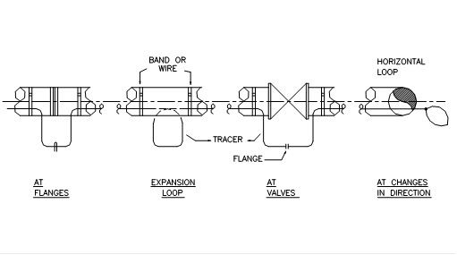
5.3.20. Loops at pipe fittings or changes in direction, valves, and flanges shall serve as expansion loops. Standard locations of tracer loops shall be as shown in figure 4.
5.4. TRAPS - STEAM TRACING SPECIFICATION
5.4.1. Steam trap installation shall be arranged to facilitate rapid and easy removal for replacement or repair of the trap.
5.4.2. Traps shall be preferable installed with the flow down, if the trap is in a horizontal run, it shall be installed on its side to prevent freezing.
5.4.3. Orientation of traps and Tail block valves to be vertical whenever practicable.
5.4.4. Traps shall be always installed to assure self-draining.
5.5. SUPPORT - STEAM TRACING SPECIFICATION
5.5.1. All manifolds, steam supply and condensate return lines; Leads and Tails piping shall be adequately supported in the field.
5.5.2. Guide clips and anchors shall be installed for tracers every 1m.
5.5.3. Anchors or guide clips shall be installed on tracers near valves, flanges, expansion loops and turns to avoid damage to insulation due to tracer expansion.
5.5.4. No provision, other than anchoring, shall be consider for expansion movement of 1/2“ and smaller tracers, since the sag or offset to take care of this amount of expansion.
5.5.5. Tracers shall be banded to process line with suitable bands tight enough to make tracers contact process line without crimping or deforming tracer tubing.
5.6. INSULATION - STEAM TRACING SPECIFICATION
5.6.1. Steam tracing piping and manifolds shall be insulated in accordance with Engineering Specification for Thermal Insulation (HOT).
5.6.2. Insulation covers shall be applied tightly around the process line, equipment and tracer. All tubing unions are to be made outside of the insulation and separately wrapped with non-asbestos ropes.
5.6.3. In all cases insulation shall be applied over the tracers.
5.6.4. Traced process lines shall be insulated with oversize insulation. Insulation oversize for steam-traced piping shall be as shown on Appendix “E”.
5.6.5. Insulation shall be slotted at expansion loops and at anchored tracer ends where the tracer leaved the process line.
5.7. IDENTIFICATION OF TRACING SYSTEM - STEAM TRACING SPECIFICATION
1) A 40mm X 50mm corrosion resistance metal identification tag plate shall be provided on DM Leads block valves, which identify the Lead block valve number, the process line number or equipment tag number, type of tracing, Tail block valve and CM number.
2) A 40mm X 50mm corrosion resistance metal identification tag plate shall be provided on CM Tail block valves, which identify the Tail block valve number, the process line number or equipment tag number, type of tracing, Lead block valve and DM number.
3) A 40mm X 50mm corrosion resistance metal identification tag plate shall be provided on tap tracing Lead and Tail block valves, which identify the Lead and/or Tail block valve number. The process line number or equipment tag number, type of tracing, steam supply header and/or condensate return header.
5.8. INSPECTION AND TESTING - STEAM TRACING SPECIFICATION
5.8.1. For steam tracing system the following visual inspection shall be made prior to insulating:
a) Tubing and pipe bends shall be visually inspected for kinked or flattened sections. All such Sections shall be cutout and replaced.
b) Tracer attachment shall be checked to insure freedom of movement towards expansion loops.
c) Tracer attachment shall be inspected at expansion loops, at equipment break points and at Other changes of direction where movement of the tracer could damage the insulation.
5.8.2. The tracing system shall be pressure tested, prior to insulation.
5.8.3. Hydrostatic test pressure shall be at least 1-1/2 times of design pressure.
Fig.3a: Standard Location of Tracer
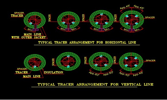
Figure 3b: Location of spacer
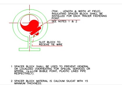
Fig.4: Standard Tracer Loops
APPENDIX “A” -STEAM TRACING SPECIFICATION
Standard Sizes, Numbers, Materials and Allowable Length of Tracers(Low Pressure Steam)
Return from Steam Tracing Specification to Industrial Inspection
Return from Steam Tracing Specification to Inspection for Industry Home
Did you find this article useful? Click on below Like and G+1 buttons!
|
|
|
Follow on
Search this Site!More than300 Articles!
Quality Control Specialist Certificate of Qualification
New!Comments
Have your say about what you just read! Leave me a comment in the box below.