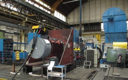
Induction Motor Testing (Routine Testing or FAT Test)
感应摩托r testing(Routine Testing or FAT Test) is performed after completion of assembly by the manufacturer to prove that the motor has the same specification as required in the purchase order.
Where a load test applicable, the efficiency is determined by IEEE 112 method E1. When the test facility is not capable of conducting a full load temperature rise test, the test is carried out at reduced power with results extrapolated to rated values. The motor test parameters such as full-load, no-load, locked rotor torque, etc. are used as defined in the IEC60034-1 and IEC60034-2.
Cold Winding Resistance Test
The purpose of this test at induction motor testing is to measure the resistance of stator, rotor and exciter windings to ensure that the values calculated at 20°C (ambient) conforms to the technical specifications. These values are used for the calculation of temperature rise. The resistances are measured by the Voltammetric method at ambient temperature.
The test is performed by a current generator (greater than 10 Adc) and a voltmeter. The acceptance criteria shall be based on manufacturer approved procedure but usually phase to phase deviation should not be more than 2%, and max deviation from theoretical value should not be more than 5%.
Temperature Sensor Resistance Test
This test is done to make sure the continuity and homogeneity of each temperature sensor defined at 100 Ohms for 0°C. A multimeter or temperature direct reading probe is used for measurement. The acceptance criteria depends on test procedure but normally should not be more than +/- 2° celsius
Bearing Temperature Test
The bearing temperature is frequently measured while the induction motor is in operation. The recorded temperature should not beyond acceptance range specified in test procedure or motor datasheet. The abnormal vibration and noise also shall be verified.
No-Load Bearing Temperature Rise
The induction motor shall run at the rated voltage and frequency, and each bearing temperature is measured periodically. Naturally, the bearing temperature will increase by passing the time. The temperature rise should not be bo more than specified value in the induction motor testing procedure or motor datasheet. The procedure determines the running time and temperature reading intervals.
No-Load Curve & Losses Characteristics @ Induction Motor Routine Testing
The rotor shall run for a while to get bearing temperature, and other variables stabilized. Then, the voltage is increased to the 120% of the rated value at the rated motor speed. Two data points are taken.
Subsequently, the voltage is decreased to 110 %, and 1 more data point is taken. This process is continued until 60 % of rated voltage, and several data points are taken. The voltage between phases, current per phase and absorbed power shall be measured at each data point. The measurement can be done by a power analyzer. The electrical calculation is made to obtain the actual losses.
The acceptance criteria shall be based on supplier approved motor routine testing procedure, but normally the calculated losses shall be less than of 110% of the theoretical loss.
Overspeed Test @ Induction Motor Testing
The overspeed test is performed to make sure that rotor speed can reach to the 1.2 times of the rated speed in 2 minutes. A speedometer is used to measure the rotor speed, and no particular noise, excess vibration and abnormal temperature rise shall be observed.
Bearing Vibration at No-Load Condition
Bearing Vibration test is performed when the rotor running at the no-load condition and the velocity vibration amplitude shall be measured in horizontal, vertical and axial directions. The velocity probe or accelerometer is used for measurement. The accelerometer measures vibration acceleration and not velocity, if used, the software converts the acceleration to the velocity by applying the calculation.
The acceptability of test shall be verified against acceptance criteria on the induction motor routine testing procedure, but the amplitude normally should not be more than 2.5 mm/s or 0.098 in/s (Root Mean Square Value).
Locked Rotor Current and Torque Test (SC/FLC & ST/FLT)
The purpose of the test in the motor routine testing is to calculate power factor, starting current and starting torque. The test is done on the locked rotor condition. The starting current might be high, and the test normally is done at lower voltage and result of the test extrapolated to the rated voltage.
A power analyzer is used for measurement. After measurement, the ratio of starting current to the full load current and starting torque to full load torques are calculated (SC/FLC & ST/FLT). The calculated values shall be verified against acceptance criteria provided in the approved in the induction motor test procedure.
Noise Level Test
The motor shall be run at the rated voltage and rotor speed at the no-load condition, and noise level should be measured at the 8 to 12 points depending on motor size and in motor premier at 1 meter distance from the motor. The noise level normally should not be more than 80 dBA, but the measured value shall be checked aginst acceptance criteria indicated in datasheet or test procedure.
Heat Run Test @ Induction Motor Testing
In this test, the machine is coupled with an appropriate rotating equipment such as the pump, fan, compressor, etc. then the load is applied to the rotor.
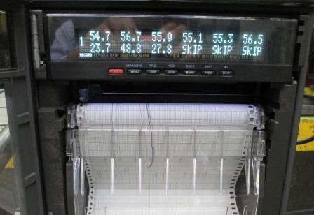
All variable such as current, voltage, power, stator temperature, bearing temperature are measured at the start and also in each 30min based on the test procedure. A power analyzer and temperature device are used for measurements.
After thermal stabilization (bearing temperatures), the motor is stopped, and hot stator resistances is measured, and temperature rise is calculated based on following parameters:
- Cold state winding temperature
- Winding temperature at test end
- Coolant temperature at test end
- Cold state stator resistance between phases
- Stator resistance between phases at the end of the test
The stator temperature rise level shall be verified based on acceptance criteria addressed in the induction motor routine testing protocol /test procedure. This test is a key test in the induction motor testing.
Insulation Resistance Test
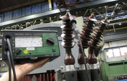
The test is one of important test in the induction motor routine testing and is done to measure the winding insulation resistance of the armature, field poles, probes, space heater and bearings (if applicable).
绕组的直流电压和联邦铁路局me to which the magnetic circuit and other windings are connected. In the case the stator capacitance is too high for the instrument the measurement can be performed phase by phase neutral open. For main windings, this measurement is performed twice, before and after the dielectric test. The measured resistance values shall be verified aginst acceptance criteria provided in the test procedure.
Return to18beplay下载
Did you find this article useful? Click on below Like and G+1 buttons!
|
|
|
Follow on
Search this Site!More than300 Articles!
Quality Control Specialist Certificate of Qualification
New!Comments
Have your say about what you just read! Leave me a comment in the box below.